
DESIGN PRINCIPLES FOR LOG BUILDINGS
FINNISH LOGHOUSE INDUSTRY ASSOCIATION (HTT) 3/2010
This guideline presents design principles for prefabricated detached log houses and other log buildings intended for continuous round-the-year use, as well as the components employed therein. The principles are also to be observed in connection with log buildings intended for part-time use, where applicable.
CONTENTS
1 TERMINOLOGY
2 MOISTURE CHARACTERISTICS OF WOOD
3 SPECIAL CHARACTERISTICS OF LOG BUILDINGS
3.1 Settling
3.2 Breathability and tightness
3.3 Durability and protection of a log wall
3.4 Lengthening of logs
4 DESIGN PRINCIPLES FOR LOG STRUCTURES
4.1 Load-bearing capacity
4.2 Energy efficiency and heat losses
4.2.1 Provisions 2008–2010
4.2.2 Provisions 2010
4.2.3 Thermal insulation characteristics of log wall
4.3 Moisture behaviour of log walls
4.4 Moisture proofing
4.5 Fire resistance of log structures
4.6 Sound-insulation capacity of a log wall
4.6.1 Uninsulated log wall
4.6.2 Log walls with additional insulation
on the inside or outside
4.7 Ventilation of buildings
5 STORAGE AT THE WORK SITE
6 CONDITIONS FOR THE LOG FRAME ERECTION
1 TERMINOLOGY
The following terms are applicable to log construction presented in this guideline.
A log is a solid building material with a thickness of at least 68 mm, produced by industrial planing or lathing and intended for use primarily in wall structures. Logs may have seal recesses and crack guiding grooves.
A rectangular log (KH) is shown in Figure1. Logs may be tongued and grooved.
A round log(Ø) is shown in Figure 2. It is round or nearly round in cross-section.
A laminated (glued) log is shown in Figure 3. It is glued together from two or more pieces with either vertical, horizontal or cross seams.
Notch jointing refers to a technique of notching logs to make a strong interlocking joint at corners.
A log intersection refers to the point at which two logs cross at right angles (see Figure 4).
A long corner is a wall or corner joint at which the ends of intersecting logs extend beyond the point of intersection.
A seal recess refers to the seam profile between the logs assembled on top of each other.
A seal refers to the packing material inserted between the logs. This is primarily to prevent unwanted air infiltration.
Dowelling refers to the method of preventing the individual logs in a wall from moving laterally. This is implemented by joining two or more logs in a perpendicular position, generally by means of wooden or steel dowels.
Cracking The characteristics of wood are subject to tangential drying shrinkage (i.e. shrinkage along the circumference of a log). This is approximately twice the radial drying shrinkage. For this reason, and because the drying begins from the surface of the wood, radial cracks develop in the log. Cracks can be guided by cutting grooves into the log.
Settling refers to the sinking of a wall due to drying shrinkage, load stresses and compression of seams.
Through-bolting refers to the use of a threaded bolt that extends over the entire height of the wall (see Figure 5) and can be tightened.
A log beam is a load-bearing beam made of one or more logs (see Figure 6).
A tongued jamb (or loose tongue) is a wooden post with (or without) a tongue that fits into a vertical groove cut into the lateral movement and allows for settling of the wall, and thus facilitates the attachment of non-settling structures, such as doors and windows. See Figures 7 and 8.
Screw-leg Some components of a log building do not settle to the same extent as the log walls.When structures are supported on these components, the settling allowance is facilitated by means of screw-legs, which can be adjusted whilst settling occurs (see Figure 9).
A settling spacer is a wooden wedge placed at the ends of wooden posts. It can be removed as the building settles.
The wall-support posts are perpendicular wooden posts, which prevent the buckling of long runs of the wall between load-bearing points. The posts are connected to each other through the wall by bolts. It is also possible to bolt a post on one side of the wall to support it.
A tenon refers to a wooden or steel dowel, which is used to dowel a log wall or a toothed plate connector made of steel, which is used to build up a log beam.
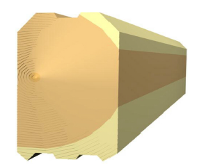
Figure 1
Example of a rectangular log profile
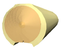
Figure 2
Example of a round log profile
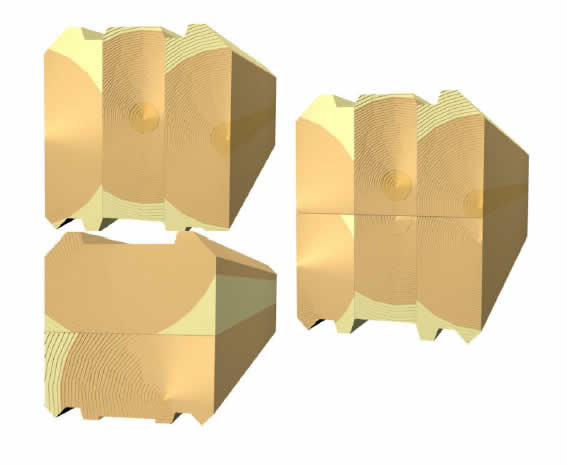
Figure 3
Example of a glued log profile
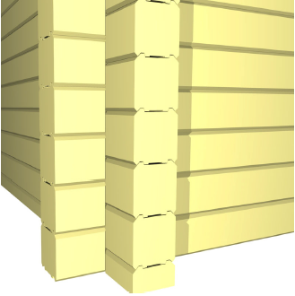
Figure 4
A log intersection
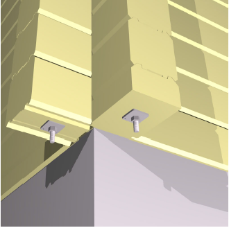
Figure 5
Through-bolting
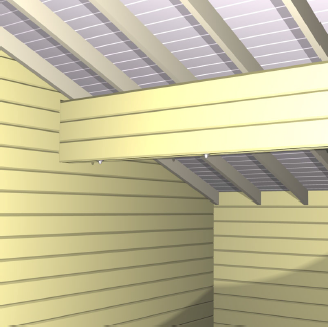
Figure 6
A log beam
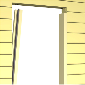
Figure 7
A tongued jamb in door opening
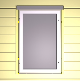
Figure 8
A window fastened to tongued jambs
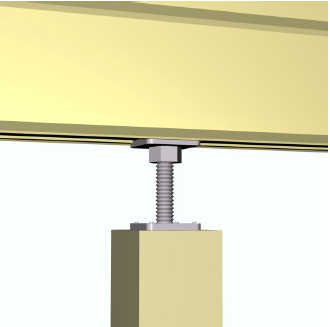
Figure 9
A screw-leg
AREAS OF A BUILDING
Net floor area (htm²) and gross floor area (kem²), calculated in accordance with the Finnish standard SFS 5139 (RT 12–10277), shall be given for each building. The areas of those parts of the building, which are not included in either of the above-mentioned areas, can be given separately. These parts of the building include galleries (gallery area), terraces (terrace area), balconies (balcony area) and cellars (cellar area).
2 MOISTURE CHARACTERISTICS OF WOOD
Wood is a hygroscopic material, meaning that its moisture content depends on the humidity (and temperature) of the air. Wood does not, however, respond quickly to changes in the relative humidity of the air. For this reason, there is little diurnal (day/night) variation in the moisture content of a log wall in the circumstances prevailing in Finland. Research has shown that moisture variation in a log takes place within a surface layer of approximately 5 cm deep on both sides of the log wall. Thus, the internal moisture of a thick wall is practically unchanged year after year once equilibrium moisture content is achieved. The final moisture content of a log in a heated interior space is approximately 8 % of dry weight and in exterior walls approximately 14 % of dry weight. In exterior walls, however, significant variation in the moisture content may occur because of exposure to direct sunlight, type of structural protection etc.
Shrinkage of wood varies in relation to the grain of the wood. Shrinkage along the longitudinal axis (parallel to the grain) is minor in comparison to shrinkage in other directions. As the wood loses its initial moisture (which is about 29 %) and dries fully, tangential shrinkage (around the circumference of the log) amounts to about 8 %, while radial shrinkage is about 4 % (see Figure 10).
Since the tangential shrinkage is twice the radial shrinkage, stresses develop in the drying wood. When these stresses exceed the wood’s tensile strength, cracks develop. The moisture content and the size of the log govern the size of the cracks. In logs with large diameters, the cracks, which result from natural drying, may be extensive. According to research, the cracks do not have any detrimental effect on thermal transmittance or stress values. Thermal transmittance is even slightly lower at a crack, owing to the stationary air within the crack.
As the relative humidity of the air changes, the width of the cracks also varies in relation to the log’s moisture content. In a heated building, the cracks on the interior side of the log are largest during the winter, when the log’s moisture content is low. In the summer the cracks are about one third smaller than in the winter. The moisture in the pith of the log at the time of construction dissipates slowly generally only after the heating of the building begins. This drying process unavoidably results in large cracks, which close up somewhat, once the pith has dried out.
3 SPECIAL CHARACTERISTICS OF LOG BUILDINGS
3.1 Settling
Settling is caused by the natural drying of wood, the compression of seams in log walls and the load stresses, and it must be taken into consideration in the design of structures. In log structures, the settling ranges from 10 to 50 mm per vertical metre, depending on the type of log. Most of this settling is due to the wood drying. In view of their lower moisture content, interior partition walls settle about 10 mm more per vertical metre than exterior walls do. When brick walls, lightweight framed partitions, staircases, fittings and posts are joined to log structures, consideration must be given to the settling of the latter.
A settling allowance must be provided for non-settling structures. If the non-settling structure is load-bearing, it must be fitted with a screw-leg. Wooden posts are fitted with settling spacers or screw-legs (see Figure 9) according to the estimated degree of settling. Consideration should also be given to the following factors during design:
• in structures supported by foundations at different levels, a greater degree of settling of legs resting on the lower foundation,
• in extending or expanding old log buildings, the fact that settling in the new and old parts of the building takes place over different periods,
• in leading ductwork through floors, ceilings and roofs, the need to ensure that fire protection clearances between the ductwork and wooden structures are maintained after settling and to allow the structures to settle without obstruction.
Light-weight framed partitions are attached to log walls by means of, for instance, battens that have elliptical slots to allow the screws to move downwards as the log structure settles (see Figure 11). Also, a framework for additional insulation is fastened to a log wall so as to allow for settling. Window and door openings are strengthened at the sides with wooden tongued jambs (or loose tongues), which are fitted into the grooves cut in the log ends. They allow the surrounding log wall to settle and prevent lateral movement of the logs (see Figures 7 and 8). In steep roofs with a log gable (i.e. the upper and lower ends of the rafters rest on the log wall), the difference in settling resulting from the height differential between the apex of the gable and the top of the gable causes the lower end of the rafters to be displaced horizontally (see Figure 13). As a consequence of this, the walls parallel to the ridge of the roof will tend to bulge outwards, unless the rafter fastenings have a mechanism to allow for this displacement. Traditionally, wooden dowelling and log intersections have been used to make log walls into rigid, integral structures. Wooden or steel dowels prevent the logs from warping out of place, especially in long walls and around openings. The distance between two dowels must not exceed 2000 mm (see Figure 14).
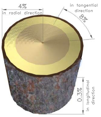
Figure 10
Drying shrinkage (%) of wood in different direction
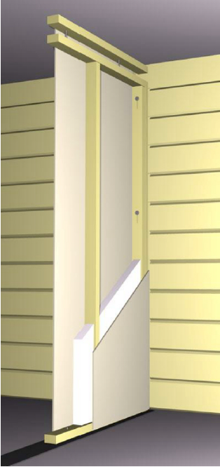
Figure 11
Connection of a light-weight framed partition to a log wall
3.2 Breathability and tightness
Log wall is a breathable structure. Breathable structure means a structure, into which water vapour can easily transfer from the surroundings by diffusion, and where water vapour can bind into a hygroscopic substance or be freed from it and be easily transferred back into the surroundings. In addition to water vapour, it is possible for other gases, such as carbon dioxide, to diffuse into the breathable structure as well. As a balancer of humidity fluctuations, the breathable structure is in a key position in terms of good and healthy indoor air. During moisture loading, water vapour is transferred into the breathable structure and is safely bound into it as hygroscopic moisture. After the moisture loading, the indoor air dries due to air ventilation, and the moisture bound into the breathable structure is released evenly back to the room air. Breathability suppresses the fluctuation of relative humidity so that the unhealthy extreme conditions of moist and dryness are avoided. The breathable structure shall possess as good air proofing qualities as any other structure. By good air proofing of the external envelope of a building, the uncontrollable airflow through structures is prevented, and controlled ventilation is guaranteed. Airproofing also prevents the water vapour from harmfully drifting with the airflow into the structures. The required air-tightness for the wall structures is achieved by shaping the recesses and by using seals between the industrially manufactured logs. The most critical matters concerning air proofing and heat consumption of a log house are the component joints of the external envelope and all feed-throughs penetrating the logs. By proper planning and accurate implementation of these factors, the conditions for good and healthy living in means of heat consumption and comfort of living are ensured.
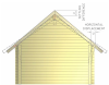
Figure 13
Movement of roof structures. The horizontal displacement U=V*tanα, where V is the settling of the gable and α is the pitch of the roof.
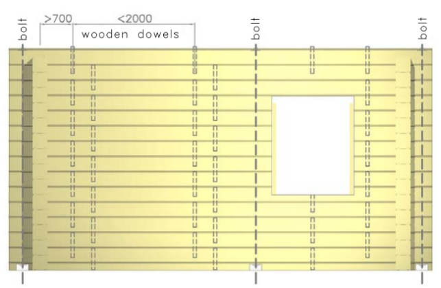
Figure 14
Dowelling of a log wall
3.3 Durability and protection of log wall
The moisture content of wood is the most important factor affecting the durability of a log. The moisture content of at least 20 % and a temperature of at least 5 °C are necessary for mould and rot fungi to develop. the moisture content of the wood exceeds the said value only when the relative humidity of the air has remained above 85 % for a long period of time.
Methods of protecting the exterior log wall.
The purpose of protecting the exterior wall of a log building is to maintain the aesthetic and structural characteristics of wood. These characteristics are deteriorated by the growth of fungi (rot and mould), dampness and by ultraviolet radiation (sunlight). The methods of protecting the log wall can be classified into three categories structural protection, chemical protection and coating. The best result is usually achieved by combining these three methods.
Structural protection
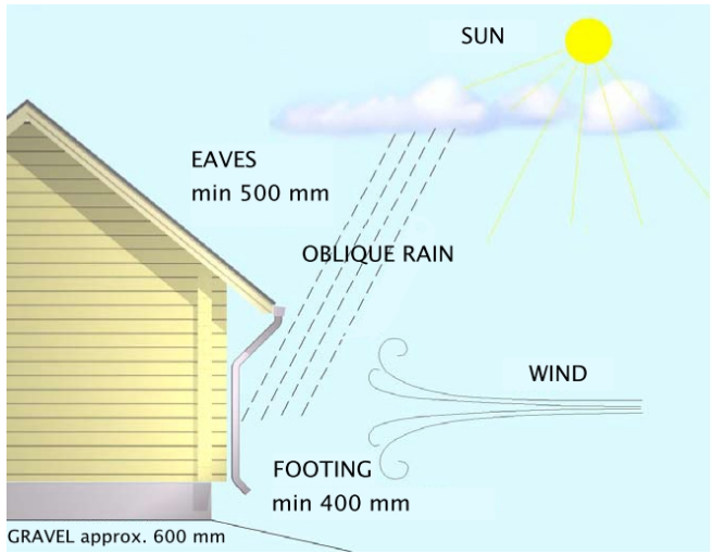
Structural protection aims at minimizing the moisture load on the surface of the log. The exterior wall should be protected against capillary water rising from the soil as well as against oblique rain and splash water. In the design of structures, consideration should be given to a free flow of air, which will dry the exterior wall efficiently. Sufficiently long eaves give effective protection against oblique rain and reduce the effect of sunlight. The eaves should be at least 500 mm long. Preferably, all terraces and balconies made of log or wooden structures should be covered. The log seam should be designed so that water running down the wall does not stay in the seam (“drip beak structure”). The packing should not extrude out of the seam, because wet packing creates favourable conditions for fungi. Gutters and downpipes guide the rainwater to the soil, preventing the wind from blowing water onto the wall. The downpipe shoe must be built so that splashing water does not hit the wall. The bottoms of window openings must be fitted with weather strips, which are tilted outwards. The footing must be sufficiently high, at least 400 mm above the soil, to prevent melted snow, water and vegetation from rotting the lowermost logs. It is absolutely necessary to cut the rise of capillary water by installing a damp course, for instance, bitumen felt or a coating of bitumen between the footing and the lowest logs.
Chemical protection and coating
Logs are treated with surface treatment agents for the following purposes:
- to protect the wood chemically against fungi (= not suitable for living)
- to fill the cells of the surface wood, thus preventing the humidity from being absorbed into the wood
- to protect the surface of the wood against ultraviolet radiation
- to form a water repulsive film on the surface of the wood.
Treatment agents are usually divided into paints and wood preservatives. Paints fill the wood more, and they form a thicker film with poorer water vapour impermeability. Wood preservatives soak deeper into the wood and they do not necessarily form any film at all on the surface of the wood. Wood preservatives generally used on log walls contain small amounts of fungicides in addition to a thinner. The surface treatment liquids are colourless, transparent or opaque. Opaque compounds are more effective than colourless or transparent compounds in protecting against ultraviolet radiation. The compounds penetrate into the wood to a depth of few millimetres. The wood preservatives may or may not form a film on the surface of the wood. It is important that the film-forming on the log is highly water vapour impermeable: Being a hygroscopic material, a solid log tends to balance the moisture content in accordance with the relative humidity of the air (this is why some paints are not suitable for log walls). If the film does not allow the water vapour to penetrate through it, the pressure of the water vapour will detach the film from the surface of the wood. Priming should be done as soon as possible after the building is constructed because ultraviolet radiation immediately penetrates into the wood to a depth of about 0,1 millimetre and starts dissociating lignin, an agglutination agent in the wood cells. The more the ultraviolet radiation dissociates lignin, the more poorly the surface treatment agent adheres to the wood. Priming also prevents the development of mould and blue rot fungi. The effect of ultraviolet radiation on South-facing walls is up to five times as great as north-facing walls. For this reason, the walls facing South and West usually need re-treating before other walls.
3.4 Lengthening of logs
Both rectangular and round logs are lengthened by finger or circular joints or by using connectors that prevent lateral and longitudinal movement of the logs. When logs are lengthened by means of connectors, the joint should preferably be located at intersecting corners. Care should be taken to ensure sufficient lateral rigidity of the wall at the lengthening joints.
4 DESIGN PRINCIPLES FOR LOG STRUCTURES
4.1 Load-bearing capacity
According to B10
Directives concerning the timber structures used in buildings are presented in Section B10 of the National Building Code of Finland (Timber structures. Guidelines. 2001). The stress grade for round logs is T30. For rectangular logs, the stress grade, unless raised by sorting is T24. Manufacture of glued and finger jointed timber for use in load-bearing structures shall take place under quality control procedures approved by the Finnish Ministry of the Environment. The loadings to be taken into account in the design of timber structures are classified on the basis of their duration into the following time classes:
A – long term
B – short-term
C – instantaneous load.
The design loading in the case of a log building generally falls within time class B. When planning the structure, consideration is given to the moisture content of the wood, which depends on the relative humidity (RH) of the air surrounding the structure. Log structures are dimensioned according to moisture class 2 unless the structure has a higher than normal moisture content. In the case of class B load duration, the stress values allowed under moisture classes 1 (internally dry) and 2 (externally dry) are the same. In a heated interior space, bending caused by the total load may not exceed a value of L/200 in the uppermost ceiling, or a value of L/300 in an intermediate or ground floor, where L is the length of the span. Also, bending caused by the live load in the ground or intermediate floor must not exceed the value of 12 mm. The bending of cantilevers in relation to the length of span maybe twice as much.
According to EC5
Eurocode 5 directives concerning timber structures are presented in standard SFSEN
1995 1-1. In Eurocode 5 strength grading, T30 corresponds to C30 and T24 corresponds to C24. Three service classes have been determined for the structures: 1, 2 and 3. Actions to be taken into consideration when planning timber structures are classified into five different load-duration classes on the basis of their duration: permanent, long-term, medium-term, short-term and instantaneous actions. With the help of the service class and load duration class, the modification factors for moisture content and load duration are chosen from the table.
Recommendations for dimensioning the load-bearing capacity of log walls
The following dimensioning recommendations are based on log wall loading tests carried out by the VTT Technical Research Centre of Finland (Report No. RTE3718/00) and the statement based on the tests.
1. The initial compression strength value is the smallest of the ultimate bearing stresses, i.e. 1,4 MPa. Based on this value, the specific bearing stress is fc,90,k = 1,0 N/mm2 .
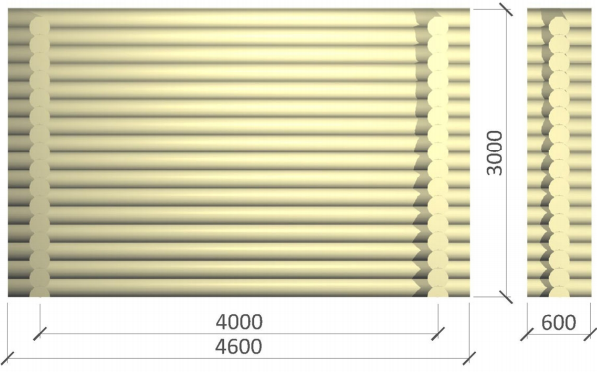
2. The maximum wall height is 3 m.
3. The minimum log intersection length must be 600 mm, but lengths exceeding this measure are not taken into account in the calculations.
4. The maximum distance between log intersections is 8 m.
5. When the distance between log intersections is 4–8 m, the capacity of the wall is equal to the capacity of a 4 m long wall.
6. The thickness of a rectangular log is ≥70 mm and that of a round log ≥130 mm. The above dimensioning recommendation can be expressed using the following formulae:
Log intersection:
F log intersection = 600 mm·fc,90,k·bef
Where bef is
0,75 · wall thickness (rectangular wall)
0,5 · wall thickness (round log).
Wall log:
F wall log = fc,90,k·L·bef,
when L≤4000 mm
tai
F wall log =fc,90,k·4000·bef
when 4000 mm< L < 8000 mm.
Wall with a log intersection:
Fwall = 2·Flog intersection + Fwall log
Example:
The thickness of the log wall with rectangular logs is 120 mm, the distance between log intersections is 5 m, and the height of the wall is 2,8 m. Log intersections are replaced by transversal walls.
Fwall = 2· F log intersection + Fwall log =2·1,0·600·0,75·120+1,0·4000·0,75·120
= 468000 N = 468 kN
This is the calculated ultimate load of the wall under test conditions.
A. Eurocode 5
When dimensioning is based on the design standards of RIL 205, the partial safety factor of material is 1,3 and the partial safety factor of the imposed load is 1,5. Value 1,2 can be used for the self-weight. For example, when the load-duration class of the load is intermediate, the factor taking the load-duration class and moisture class into consideration is kmod = 0,8 in moisture classes 1 and 2. This yields the maximum nominal load (”permitted” load) affecting the wall as follows:
Fk = (0,8·468):(1,5·1,3) = 192 kN
Calculated per one length unit of the wall, this is
qk = 192/5 = 38,4 kN/m
B. Limit state analysis
The limit state analysis (load-duration class B, moisture class 1), using the timeeffect factor of the material k = 1,3, yields the following calculated load:
Fwall = 468/1,3 = 360 kN.
Hence qk = 360/5 = 72 kN/m
C. Permitted stresses
The calculated based on permitted stresses yields the following permitted load for the wall:
Fwall = 360/(1,3·1,6) = 173 kN.
Hence qperm = 173/5 = 34,6 kN/m.
4.2 Energy efficiency and heat losses
4.2.1 Provisions 2008–2010
From the beginning of the year 2008 new rules regarding energy efficiency and heat losses of the building became valid. Those are covered in the following sections of the National Building Code of Finland
C3 Thermal insulation in a building, Regulations 2007
C4 Thermal insulation, Guidelines 2003>
D2 Indoor climate and ventilation of buildings, Regulations and guidelines
D3 Energy management in buildings, Regulations and guidelines 2007
D5 Calculation of power and energy needs for heating of buildings, Guidelines 2007
Regulations concern also the holiday houses meant for all-year use, as well as other buildings of permanent living. In the calculations of the building’s heat losses, the entirety of the building’s exterior envelope, airflow and ventilation is examined. Calculated heat loss can be at maximum as high as the regulation conforming reference heat loss value determined for building. Regulation conformity is verified with the compensation calculation of heat losses.
Compensation calculations of heat losses
Some components of the building (external envelope, airflow, ventilation) may have a greater heat loss value than the reference heat loss value. This weaker component can be compensated by replacing one component with absolution better than regulations. Regulation conformity is thereby verified with the compensation calculation of heat losses. Detailed instructions for the compensation calculations are presented in the guidelines published by the Ministry of the Environment; “Tasauslaskentaopas 2007, Rakennuksenlämpöhäviön määräystenmukaisuuden osoittaminen” (free translation: Guidelines for compensation calculations 2007. Verifying the regulation conformity of the building’s heat losses). Guidelines include an example calculation for a log house as well.
Provisions for thermal insulation
In principle, the overall heat transfer coefficients (U-values) of the components of the residential buildings shall not exceed the following values:
Exterior wall 0,24 W/m2K
Roof, susbended beam floor 0,15 W/m2K
Slab-on-ground/ground floor 0,24 W/m2K
Ventilated ground floor (ventilation openings 8 ‰ at maximum) 0,19 W/m2K
Window/exterior door 1,40 W/m2K
Skylight window 1,50 W/m2K
The overall heat transfer coefficient of wall, roof or ground floor may be, however, 0,6 W/m2K and/or that of window’s 1,8 W/m2K, if other parts of the building are insulated more tightly, respectively. When calculating the reference heat loss value of a building, leakage air = 0,16 l/h is used as the air leakage coefficient, which corresponds to the air leakage rate n50 = 4,0 l/h. A smaller rate may be used if airtightness can be proved by measurements or some other method. When calculating the reference heat loss, 30 % is used as the yearly efficiency ratio for the heat recovery of ventilation.
4.2.2 Provisions 2010
From the beginning of 2010 new rules regarding energy efficiency and heat losses of the building became valid. Those are covered in the following sections of the National Building Code of Finland
· C3 Thermal insulation in a building, Regulations 2010
· D2 Indoor climate and ventilation of buildings, Regulations and guidelines 2010
· D3 Energy management in buildings, Regulations and guidelines 2010
Regulations of the year 2010 concern the same buildings as the previous regulations. Examination of the building’s heat losses and verifying their conformity with the regulations is performed similarly with compensation calculations as in provisions of the year 2008.
Provisions for thermal insulation
As a new regulation for the log walls at least 180 mm thick, is the specific reference value of the overall heat transfer coefficient. In principle, the overall heat transfer coefficients (U-values) of the components of the residential buildings shall not exceed the following values:
Exterior wall 0,24 W/m2K
Roof, susbended beam floor 0,15 W/m2K
Slab-on-ground/ground floor 0,24 W/m2K
>Ventilated ground floor (ventilation openings 8 ‰ at maximum) 0,19 W/m2K
Window/exterior door 1,40 W/m2K
Skylight window 1,50 W/m2K
The overall heat transfer coefficient of wall, roof or ground floor may be, however, 0,6 W/m2K and/or that of window’s 1,8 W/m2K, if other parts of the building are insulated more tightly, respectively.
When calculating the reference heat loss value of a building, leakage air = 0,08 l/h is used as the air leakage coefficient, which corresponds to the air leakage rate n50 = 2,0 l/h. A smaller rate may be used if airtightness can be proved by measurements or some other method. When calculating the reference heat loss, 45 % is used as the yearly efficiency ratio for the heat recovery of ventilation.
4.2.3 Thermal insulation characteristics of log wall
The mean thickness of a solid log wall must be approximately 180 mm (λn = 0,12 W/mK) in order to meet the U-value requirement of 0,60 W/m2K. For a round log wall, it is necessary to calculate a so-called geometric equivalent thickness, i.e. the thickness that corresponds to the thickness of a rectangular log wall with uniform thickness. Geometric equivalent thickness can be calculated with formula: Geometric equivalent thickness = A/h
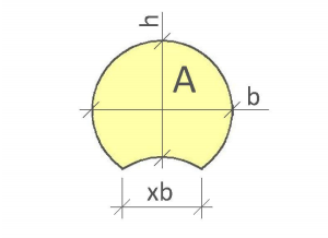
h = diameter – height of recess
A = cross-section area of a round log
b = diameter
xb = width of recess
If the width of recess is assumed to be 0,5b, the equivalent thickness is 0,855b. With a recess width of 0,6b, the equivalent thickness is 0,800b. Normative U-values for different log types and log walls with additional insulation are presented in Table 4.
Table 4.
Normative u-values (W/m2K) for wall structures with and without additional thermal insulation (log λn= 0,12 W/mK, wool λn = 0,037).
HH = rectangular log and Ø = round log
| Log mm | Log Insulation, mm | |||||
| 0 | 50 | 75 | 100 | 125 | 150 | |
| HH70 | 1,33 | 0,48 | 0,39 | 0,31 | 0,26 | 0,23 |
| HH95 | 1,04 | 0,43 | 0,36 | 0,29 | 0,25 | 0,22 |
| HH110 | 0,92 | 0,41 | 0,35 | 0,28 | 0,24 | 0,21 |
| HH120 | 0,85 | 0,4 | 0,34 | 0,27 | 0,23 | 0,2 |
| HH135 | 0,77 | 0,38 | 0,32 | 0,26 | 0,22 | 0,19 |
| HH180 | 0,6 | 0,34 | 0,27 | 0,23 | 0,2 | 0,18 |
| HH205 | 0,53 | 0,31 | 0,26 | 0,22 | 0,19 | 0,17 |
| HH270 | 0,41 | 0,27 | 0,24 | 0,2 | 0,18 | 0,16 |
| Ø130 | 0,89 | 0,4 | 0,32 | 0,26 | 0,22 | 0,19 |
| Ø150 | 0,79 | 0,38 | 0,3 | 0,25 | 0,22 | 0,19 |
| Ø170 | 0,72 | 0,36 | 0,29 | 0,24 | 0,21 | 0,18 |
| Ø190 | 0,64 | 0,34 | 0,28 | 0,23 | 0,2 | 0,18 |
| Ø210 | 0,58 | 0,33 | 0,27 | 0,23 | 0,2 | 0,17 |
| Ø230 | 0,53 | 0,31 | 0,26 | 0,22 | 0,19 | 0,17 |
4.3 Moisture behaviour of log walls
Solid log walls
For moisture control, a solid log wall with no additional insulation is a safe and secure solution, provided that the building is equipped with proper structural protection. The moisture content of a log wall varies depending on the relative humidity of the air. At its maximum, the average variation is in the range of one percent (or slightly higher for smaller log thicknesses). The seasonal variation in the moisture content of wood is greatest in the layer extending to a depth of 5 cm from the internal and external surface of the log.
Log walls with additional insulation
The moisture control of a log wall with additional insulation is a far more complex issue. Thermal insulation of the inside of the log wall is not recommended unless a vapour barrier is installed. Internal thermal insulation without a vapour barrier can be used, provided that the thickness of the insulation does not exceed 50 mm. In this case, the structure must contain bitumen paper or similar material serving as an air barrier. If the internal thermal insulation is thicker than 50 mm, it is necessary to use a sufficiently tight vapour barrier. If there is a ventilation gap between the insulation and the log, the thermal insulation properties inherent to the log cannot be exploited in the thermal insulation of the log building. Inverted structure (i.e. additional insulation on the outside) is problem-free as far as moisture control is concerned because the log is then on the warmer and drier side of the structure. In this kind of structure, it is necessary to have an air gap between the thermal insulation and the external cladding to allow the moisture possibly accumulating in the insulation to dry out. This also prevents the moisture penetrating through the cladding from reaching the thermal insulation.
4.4 Moisture proofing
Section C2 of the National Building Code of Finland (Humidity. Regulations and instructions. 1998.) lays down the regulations for moisture control of buildings. The structures should be such that they are not detrimentally affected either by rainwater, snowmelt and ground moisture penetrating from the outside, or water vapour originating within the building. Particular attention should be paid to the following points:
· Concrete may not be cast directly against wood without a moisture seal.
· The bottom of the log wall should be at least 400 mm above the surface of the ground.
· Showers and other water fixtures should not be installed on non-protected log walls.
· Water and moisture seals must be installed with particular attention and care, and in accordance with the manufacturer’s instructions
4.5 Fire resistance of log structures
Section E1 of the National Building Code of Finland (Structural Fire Safety. Regulations. 2002) contains the fire safety regulations for buildings. Construction materials are divided into classes according to their impact on fire ignition, spreading and smoke generation. Log is classified into class D-s2, d0. Notation D means that the material’s contribution to fire is within acceptable limits, s2 means that smoke generation is minimal, and d0 means that burning droplets or separate parts do not occur. Requirements appointed at building components are described with the following notations:
R load-bearing capacity
E tightness
I insulation capacity
Fire resistance time of a log wall when it functions as a compartment component (EI) is presented in table 5. Bearing capacity tests have been completed at VTT in accordance with SFS-EN 1365- 1:1999 standard. In addition, the following expectations are set on different log types.
Laminated log walls
· Seam shall be tongued and grooved, with a tongue height 10 mm in minimum in fire resistance classes R30 and EI30 and 12 mm in fire resistance classes R120 and EI90. Intermediate values are interpolated.
· Seam sealing between the logs is polypropylene tape or glass wool strip in fire resistance classes R30 and EI30, and in fire resistance classes above that glass wool strip, which is at least 2 mm thicker than the groove. Transversal walls shall be sealed with glass wool strip according to the structures presented in reports RTE699/05 and, RTE3924/04. Other materials, whose combustion properties correspond to the properties of the above-mentioned materials, can be used as sealing as well.
· Distance between the wooden dowels in the wall can be 1600 mm at maximum.
Round log walls
· Seam between the logs is the same kind as in report RTE863/05 and the distance 3 mm at maximum.
· Seams between the logs shall be sealed with similar polyurethane tape as in report RTE863/05 and the thickness of the tape shall be a couple of millimetres bigger than the space in between. Transversal walls shall be sealed in accordance with the same report. Other materials, whose combustion properties correspond to the properties of the above-mentioned materials, can be used as sealing as well.
· Distance between the wooden dowels in the wall can be 1200 mm at maximum.
Rectangular log walls with additional insulation
· Seam must be a tongued and grooved joint, with a tongue height 10 mm in minimum.
· Seam sealing between the logs is polypropylene tape or glass wool strip, which is at least 2 mm thicker than the groove itself. Transversal walls shall be sealed with glass wool strip according to the structures presented in report RTE4234/04. Other materials, whose combustion properties correspond to the properties of the above-mentioned materials, can be used as sealing as well.
· Distance between the wooden dowels in the wall can be 1600 mm at maximum.
Table 5
Fire resistance of load-bearing laminated walls, round log walls and rectangular log walls with additional insulation, in relation to load-bearing capacity R and compartment EI with walls of differing thicknesses when the concentric load of the wall is 9,4 kN/m at maximum. In the table is given the minimum size for the joint width as well.
| Laminated log | R30 | R60 | R90 | R120 |
| width x height [mm²] | 92 x 170 | 138 x h 1) | 180 x h 1) | n/a |
| joint width [mm] | 70 | 116 | 156 | n/a |
| EI30 | EI60 | EI90 | EI120 | |
| width x height [mm²] | 92 x 170 | 148 x h 1) | 199 x h 1) | n/a |
| joint width [mm] | 70 | 126 | 175 | n/a |
| 1) h = 170 mm - 195 mm | ||||
| Round Log | R30 | R60 | R90 | R120 |
| Log diameter [mm] | 150 | 236 | n/a | n/a |
| Joint width [mm] | 81 | 127 | n/a | n/a |
| EI30 | EI60 | EI90 | EI120 | |
| Log diameter [mm] | 150 | 236 | n/a | n/a |
| Joint width [mm] | 81 | 127 | n/a | n/a |
| Rectangular log + insulation + log panel | R30 | R60 | R90 | R120 |
| width x height [mm²] | b x 170 2), 3) | 128 x 170 3) | n/a | n/a |
| joint width [mm] | b-22 | 106 | n/a | n/a |
| EI30 | EI60 | EI90 | EI120 | |
| width x height [mm²] | b x 170 2), 3) | 128 x 170 3) | n/a | n/a |
| joint width [mm] | b-22 | 106 | n/a | n/a |
2) Width b according to normal temperature design
3) The fire side of the rectangular log wall requires insulation and log panel in addition, according to
the test report RTE 4234/04, load concentrically in relation to the log.
4.6 Soundproofing of log walls
Airborne soundproofing value Rw is informed as airborne soundproofing values against road traffic noise Rw + Ctr or against rail and air traffic noise Rw + C. In town, the regulation concerning the sound insulation properties of the building's external envelope is given as the difference between the sound levels prevailing at the exterior envelope and the sound levels permitted inside the building. For example, by means of the procedure presented in the Environmental guide 108, published by the Ministry of the Environment, it is possible to derive the airborne soundproofing values for the construction components from the sound level differences of the plan provision. The sound insulation capacity of a log wall depends on the wall mass, its rigidity and the tightness of its seal recess, for instance. Airborne soundproofing values for the thinnest log structures against traffic noise are low. Differences in the sound levels requested in the plan provisions are usually 28 dB at the minimum and 40 dB at the maximum. In log building, it is possible to achieve the sound difference of approximately 28–30 dB, if normal window structures and log types GL180 and GL205 are used. With a log wall with additional insulation, it is also possible to achieve the required soundproofing levels. The sound insulation capacity of other structures is probably inadequate.
Table 5
Calculated sound insulation values (dB).
| Log | Rw | Rw + C | Rw + Ctr |
| HH95 | 33 | 31 | 28 |
| HH112 | 34 | 32 | 29 |
| HH120 | 35 | 34 | 31 |
| HH135 | 36 | 34 | 32 |
| HH180 | 39 | 37 | 36 |
| HH205 | 40 | 38 | 37 |
| HH270 | 40 | 39 | 39 |
| Ø150 | 30 | 29 | 26 |
| Ø170 | 31 | 29 | 26 |
| Ø190 | 32 | 31 | 27 |
| Ø210 | 33 | 32 | 29 |
| Ø230 | 37 | 35 | 33 |
4.6.1 Uninsulated log walls
Uninsulated log walls consist of one log layer. From the perspective of acoustic functioning, uninsulated log walls are simple structures, whose sound insulation properties are determined especially by the mass [kg/m2 ] of the structure and the barrier frequency of the structures coincidence, which in turn depends on the mass and rigidity of the structure.
4.6.2 Log walls with additional insulation on the inside or outside
From the perspective of acoustic functioning, the structure is a double structure, whose halves are connected to each other by rails. The soft and porous thermal insulation between the rails has an essential effect on the sound insulation properties of the wall. Without the thermal insulation, the sound insulation capacity would be 3–5 dB lower. Mineral wool and wood fibre insulation, on the other hand, do not differ in means of sound insulation.
4.7 Ventilation of buildings
Regulations governing ventilation are presented in Section D2 of the National Building Code of Finland (Indoor climate and ventilation in buildings. Regulations and guidelines 1987. Available in English.). A satisfactory internal climate in spaces where people are normally present should be assured under all normal weather conditions and under the conditions of use particular to each space. The purity, temperature and humidity of the internal climate should be controlled. In places normally occupied by people, draughts and noise that would be detrimental to the comfort of the occupants are not permitted There must be adequate ventilation so that condensation of moisture in the structures will not cause moisture
damage. Incoming air may be brought into a room space through the building’s external envelope or as transferred air. In buildings designed for all-year use, thermal insulation provisions require that the heat recovery of the air conditioning appliances is taken into consideration.
Table 7.
| RW | RW + C | RW=+Ctr | |||||||||||||||
| Log [mm] | 45 | 95 | 120 | 145 | 195 | 45 | 95 | 120 | 145 | 195 | 45 | 95 | 120 | 145 | 195 | ||
| HH95 | 45 | 47 | 48 | 49 | 49 | 41 | 45 | 46 | 47 | 48 | 36 | 41 | 42 | 43 | 45 | ||
| HH112 | 46 | 48 | 49 | 49 | 50 | 42 | 46 | 47 | 48 | 49 | 36 | 41 | 43 | 43 | 46 | ||
| HH120 | 47 | 49 | 50 | 50 | 50 | 43 | 47 | 48 | 49 | 50 | 38 | 43 | 44 | 45 | 47 | ||
| HH135 | 47 | 49 | 50 | 51 | 51 | 44 | 48 | 49 | 50 | 50 | 40 | 44 | 46 | 47 | 48 | ||
| HH180 | 50 | 53 | - | - | - | 48 | 52 | - | - | - | 43 | 48 | - | - | - | ||
| HH205 | 51 | 53 | - | - | - | 50 | 53 | - | - | - | 45 | 50 | - | - | - | ||
| HH270 | 53 | - | - | - | - | 52 | - | - | - | - | 49 | - | - | - | - | ||
| Ø150 | 44 | - | - | - | - | 40 | - | - | - | - | 36 | - | - | - | - | ||
| Ø170 | 44 | - | - | - | - | 40 | - | - | - | - | 35 | - | - | - | - | ||
| Ø190 | 45 | - | - | - | - | 41 | - | - | - | - | 36 | - | - | - | - | ||
| Ø210 | 45 | - | - | - | - | 41 | - | - | - | - | 36 | - | - | - | - | ||
| Ø230 | 48 | - | - | - | - | 45 | - | - | - | - | 40 | - | - | - | - |
| RW | RW +C | RW =+Ctr | |||||||||||||||
| Log [mm] | 45 | 95 | 120 | 145 | 195 | 45 | 95 | 120 | 145 | 195 | 45 | 95 | 120 | 145 | 195 | ||
| HH95 | 49 | 51 | 52 | 52 | 53 | 45 | 50 | 51 | 51 | 51 | 40 | 46 | 47 | 48 | 49 | ||
| HH112 | 50 | 52 | 53 | 53 | 53 | 46 | 51 | 51 | 52 | 52 | 41 | 46 | 48 | 49 | 50 | ||
| HH120 | 50 | 53 | 53 | 53 | 54 | 48 | 52 | 52 | 52 | 53 | 43 | 48 | 49 | 50 | 50 | ||
| HH135 | 50 | 53 | 54 | 54 | 54 | 49 | 52 | 53 | 53 | 53 | 44 | 49 | 50 | 51 | 51 | ||
| HH180 | 54 | 56 | - | - | - | 52 | 55 | - | - | - | 48 | 52 | - | - | - | ||
| HH205 | 55 | 56 | - | - | - | 54 | 55 | - | - | - | 50 | 54 | - | - | - | ||
| HH270 | 56 | - | - | - | - | 56 | - | - | - | - | 54 | - | - | - | - | ||
| Ø150 | 48 | - | - | - | - | 45 | - | - | - | - | 41 | - | - | - | - | ||
| Ø170 | 48 | - | - | - | - | 45 | - | - | - | - | 41 | - | - | - | - | ||
| Ø190 | 49 | - | - | - | - | 46 | - | - | - | - | 41 | - | - | - | - | ||
| Ø210 | 49 | - | - | - | - | 45 | - | - | - | - | 40 | - | - | - | - | ||
| Ø230 | 52 | - | - | - | - | 50 | - | - | - | - | 45 | - | - | - | - |
| RW | RW +C | RW =+Ctr | |||||||||||||||
| Log [mm] | 45 | 95 | 120 | 145 | 195 | 45 | 95 | 120 | 145 | 195 | 45 | 95 | 120 | 145 | 195 | ||
| HH95 | 43 | 46 | 48 | 48 | 49 | 40 | 43 | 44 | 46 | 47 | 35 | 37 | 39 | 41 | 43 | ||
| HH112 | 44 | 47 | 48 | 49 | 50 | 41 | 43 | 45 | 46 | 48 | 36 | 38 | 40 | 42 | 44 | ||
| HH120 | 44 | 48 | 49 | 50 | 51 | 42 | 45 | 47 | 48 | 49 | 37 | 40 | 42 | 43 | 45 | ||
| HH135 | 45 | 48 | 49 | 50 | 51 | 43 | 46 | 48 | 49 | 50 | 38 | 41 | 43 | 45 | 47 | ||
| HH180 | 50 | 52 | - | - | - | 47 | 50 | - | - | - | 42 | 46 | - | - | - | ||
| HH205 | 51 | 53 | - | - | - | 49 | 52 | - | - | - | 45 | 48 | - | - | - | ||
| HH270 | 53 | - | - | - | - | 52 | - | - | - | - | - | 48 | - | - | - | - | |
| Ø150 | 42 | - | - | - | - | 38 | - | - | - | - | - | 33 | - | - | - | - | |
| Ø170 | 42 | - | - | - | - | 38 | - | - | - | - | - | 34 | - | - | - | - | |
| Ø190 | 42 | - | - | - | - | 39 | - | - | - | - | - | 34 | - | - | - | - | |
| Ø210 | 43 | - | - | - | - | 40 | - | - | - | - | - | 35 | - | - | - | - | |
| Ø230 | 46 | - | - | - | - | 42 | - | - | - | - | - | 39 | - | - | - | - |
Table 10.
| RW | RW +C | RW =+Ctr | |||||||||||||||
| Log [mm] | 45 | 95 | 120 | 145 | 195 | 45 | 95 | 120 | 145 | 195 | 45 | 95 | 120 | 145 | 195 | ||
| HH95 | 39 | 42 | 43 | 44 | 45 | 37 | 38 | 39 | 40 | 42 | 32 | 33 | 34 | 35 | 36 | ||
| HH112 | 40 | 43 | 43 | 44 | 46 | 38 | 39 | 40 | 40 | 43 | 33 | 34 | 34 | 35 | 37 | ||
| HH120 | 41 | 43 | 44 | 45 | 47 | 39 | 41 | 41 | 42 | 44 | 34 | 35 | 36 | 37 | 39 | ||
| HH135 | 42 | 44 | 45 | 46 | 47 | 40 | 42 | 43 | 44 | 46 | 36 | 37 | 38 | 38 | 40 | ||
| HH180 | 46 | 49 | - | - | - | 44 | 46 | - | - | - | 39 | 41 | - | - | - | ||
| HH205 | 48 | 50 | - | - | - | 46 | 48 | - | - | - | 41 | 43 | - | - | - | ||
| HH270 | 52 | - | - | - | - | 50 | - | - | - | - | 45 | - | - | - | - | ||
| Ø150 | 37 | - | - | - | - | 35 | - | - | - | - | 30 | - | - | - | - | ||
| Ø170 | 38 | - | - | - | - | 35 | - | - | - | - | 31 | - | - | - | - | ||
| Ø190 | 38 | - | - | - | - | 36 | - | - | - | - | 31 | - | - | - | - | ||
| Ø210 | 39 | - | - | - | - | 37 | - | - | - | - | 32 | - | - | - | - | ||
| Ø230 | 43 | - | - | - | - | 41 | - | - | - | - | 36 | - | - | - | - |
5 STORAGE AT THE WORK SITE
Timber can usually be stored outside, provided that it is protected against sunlight, rainwater and moisture from the ground. The goods stored outside must be at a height of at least 30 cm from the ground in order to prevent the ground moisture and vegetation from damaging the timber. To obtain sufficient stability and to prevent bending or warping due to storage, the dimension between the supporting boards should not exceed 1,5 metres. Care should be taken to prevent water from pooling below the timber. There should be a sufficient number of tarpaulins used in storage because the transportation protection is not intended for long-term exposure to weather. The timber should be covered so that air circulation is ensured. While the tarpaulin should expand over the ends of boards and logs, it must not reach the ground. When stacking timber, transversal battens between the bundles and logs should be used. This allows proper circulation of the air and conduction of excessive moisture.
6 CONDITIONS FOR THE LOG FRAME ERECTION
Packing material should not be allowed to get damp during the course of erection since wet packing facilitates the growth of fungi. Any pieces of packing that are exposed outside the seal recess should be cut away each working day, so as to avoid dampness. The frame should be protected against persistent rain during construction. For long-term protection, and when the air is damp, care must be taken to maintain adequate ventilation under the tarpaulins. Furthermore, particular attention must be given to ventilation once the erection work is completed, since moisture escaping from the structures may condense and cause, for instance, blue staining. The erection instructions provided by the manufacturer should be followed.
HTT-PUBLICATIONS:
In co-operation with authorities, the Finnish Loghouse Industry Association (HTT) has published the following guidelines: Hirsitalojen toimitusehdot (’Terms and conditions of delivery for log buildings’).
A BRIEF HISTORY OF LOG BUILDINGS
Construction of log buildings has, for natural reasons, evolved in the coniferous forest zone. The earliest log buildings with notched, intersecting corners, date from the Iron and Bronze Ages. Although in Switzerland, there are horizontal log structures dating back to the Stone Age. In Finland, the oldest log building still existing is a chapel dedicated to St. Henry, situated in Kokemäki, South-Western Finland. It was built around the year 1400. After World War I, board-clad timber-framed houses rapidly gained popularity in Finland. In the countryside, however, log maintained its position as the primary building material up until the 1940s, but then its use in round-the-year houses declined little by little until it almost came to a complete stop. On the other hand, log has always been the dominating material for summer cabins. Today about 70 percent of new leisure homes in Finland are built of log. In the early 1950s, industrial log production expanded in Finland.
Initially, the development work focused almost solely on the production process. Gradually, more attention was devoted to the product itself. The 1970s and 1980s were an era of vigorous development for log houses as an industrial product. The industry looked intensely for solutions to deal with sealing, insulation and compression problems, and the development of prefabricated log building continues today. In addition to the continuous development, the favourable environmental impacts of log and healthiness are emphasized in the selection criteria of homebuilders. Almost 90 percent of all log houses built in Finland today are prefabricated, i.e. industrially manufactured. Modern computer-aided industrial prefabrication allows, for instance, pre-drying of logs, resulting in the highest possible dimensional accuracy. As the log frame can be erected on-site in just a few days, the house is quickly constructed and protected against the weather. Prefabricated log buildings made in Finland even attract attention abroad: In 2009, log buildings were exported to over 60 countries. Finland is the leading manufacturer of prefabricated log building